Yes, if the ceiling detail is designed for the complete system
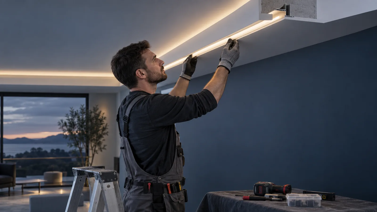
LED strip can be installed in a gypsum or plasterboard ceiling as indirect cove lighting, inside a recessed aluminum profile, or behind a removable trim. The strip should not simply be stuck to unfinished board and sealed into the ceiling. A dependable detail provides a smooth mounting surface, enough space for the profile and diffuser, a sensible cable route, and access to drivers and connections after painting is complete.
Decide the lighting effect before the ceiling contractor closes the frame. Indirect coves hide the light source and wash a surface. Recessed profiles produce a visible linear aperture. These two details need different setback, profile depth and diffuser choices. A line that looks continuous on a sample board can show dots or dark joints once the viewing angle changes in the finished room.
The product, driver, dimmer, profile, ceiling section and access panels form one system. Approving only the LED reel leaves the most common site risks unresolved.
Choose the ceiling detail before choosing the reel
Indirect gypsum cove
A cove places the strip behind a gypsum lip so occupants see reflected light. The setback from the wall or ceiling and the height of the lip determine how wide and even the wash appears. A shallow cove can create a bright line near the source and a dark band farther away. A deep cove may absorb too much light.
Build a full-size section with the intended paint finish. Test the strip at the lowest and highest dimming levels from normal viewing positions. Include inside and outside corners, because these often reveal gaps that a straight sample does not show.
Mount the strip in an aluminum profile or on another approved heat-spreading surface. Raw joint compound, dusty board and fresh paint are unreliable adhesive bases. The profile also gives the installer a straight reference and makes replacement more predictable.
Recessed linear profile
A recessed profile is set into the ceiling so its diffuser finishes flush or nearly flush with the surface. Select the profile before forming the slot. Its external width, flange, depth, clip method and end-cap allowance must match the framing and finish build-up.
The internal width must accommodate the PCB, solder joint and any connector. The diffuser-to-LED distance affects dot visibility. A dense COB strip may produce a smoother line in a shallow profile, while an SMD strip may need more depth or a more diffusing cover. Compare the 8mm COB CRI95 model and the 8mm SMD2835 CRI98 model only after confirming the required output, CCT, power and profile geometry for the project.
LEDVANCE publishes separate instructions for a drywall recessed linear system. The manual illustrates why the profile, mounting brackets, ceiling opening and finishing sequence must be coordinated as a system. Follow the instructions for the exact profile selected on site.
Plan voltage, drivers and service access
Place drivers where they can be inspected and replaced without cutting the ceiling. A removable access panel, nearby cabinet or serviceable ceiling void is preferable to burying equipment behind finished gypsum. Keep mains connections inside suitable enclosures and use qualified electrical personnel for fixed wiring.
Prepare a circuit schedule for each ceiling zone:
- strip model, voltage and watts per meter;
- installed length on each feed;
- calculated connected load and driver loading rule;
- cable route, conductor size and expected voltage drop;
- feed point and any double-end or intermediate injection;
- dimming method and controller compatibility;
- driver and junction-box access location;
- emergency or building-control interface, if applicable.
For a strip rated at 12W/m, a 7m branch has a nominal strip load of 84W before allowing for driver selection, cable loss or project-specific derating. Do not place several long branches on one driver merely because their combined label wattage is below the driver’s headline rating. Check output terminals, branch protection, wiring, ambient temperature and the manufacturer’s loading guidance.
The LEDVANCE strip-system installation guide calls for installation on a clean, dry mounting surface and shows system-specific cutting, connectors and profiles. It is useful as a coordination example; use the instructions supplied with the ordered strip and accessories for the actual installation.
Coordinate the trades in this order
- Mark the luminous line on the reflected ceiling plan and approve the cove or recessed section.
- Confirm framing, profile support, access panels, cable routes and driver locations before board installation.
- Build one representative mock-up using the actual strip, profile, diffuser, driver, dimmer and paint color.
- Test brightness, color, glare, dot visibility, dimming and reflected-light uniformity from normal viewing positions.
- Install and finish the gypsum detail without filling, painting or deforming the profile opening.
- Remove dust and prepare the profile surface according to the strip backing instructions.
- Cut only at marked points and make joints without twisting the PCB or placing tension on copper pads.
- Support cables separately, fit diffusers and keep soldered or connector joints accessible where the detail permits.
- Energize each branch at its rated voltage. Inspect start-to-end brightness, dimming, color match and temperatures under normal load.
- Record driver locations, circuit assignments and replaceable lengths for handover.
Do not install the LED reel during sanding or painting. Gypsum dust can contaminate adhesive, connectors and diffusers. Paint overspray changes light transmission and makes future servicing difficult.
Five failures to catch at the mock-up
The light line shows bright and dark sections
Possible causes include inconsistent setback, a shallow profile, visible cut joints, voltage loss or a diffuser that does not mix the source adequately. Measure the physical detail and loaded voltage before blaming the LED batch.
The strip releases from the ceiling
Dust, uncured paint, rough gypsum, cable pull and high operating temperature can all weaken the bond. Use a clean aluminum profile, prepare it correctly and secure cables so they do not peel the strip away.
The ceiling has to be cut open for a failed driver
This is a planning fault. Mark every driver and junction point on the as-built drawing and prove that each can be reached with ordinary service tools.
Corners look broken
Do not force the PCB around a corner tighter than its permitted bend. Plan cut-and-wire joints, approved connectors or separate straight sections. Check that joints remain hidden from the main viewing angle.
The color looks wrong after painting
The reflected result depends on both CCT and surface color. Approve the sample against the final paint, timber, stone and fabrics. A white test board cannot predict every finished interior.
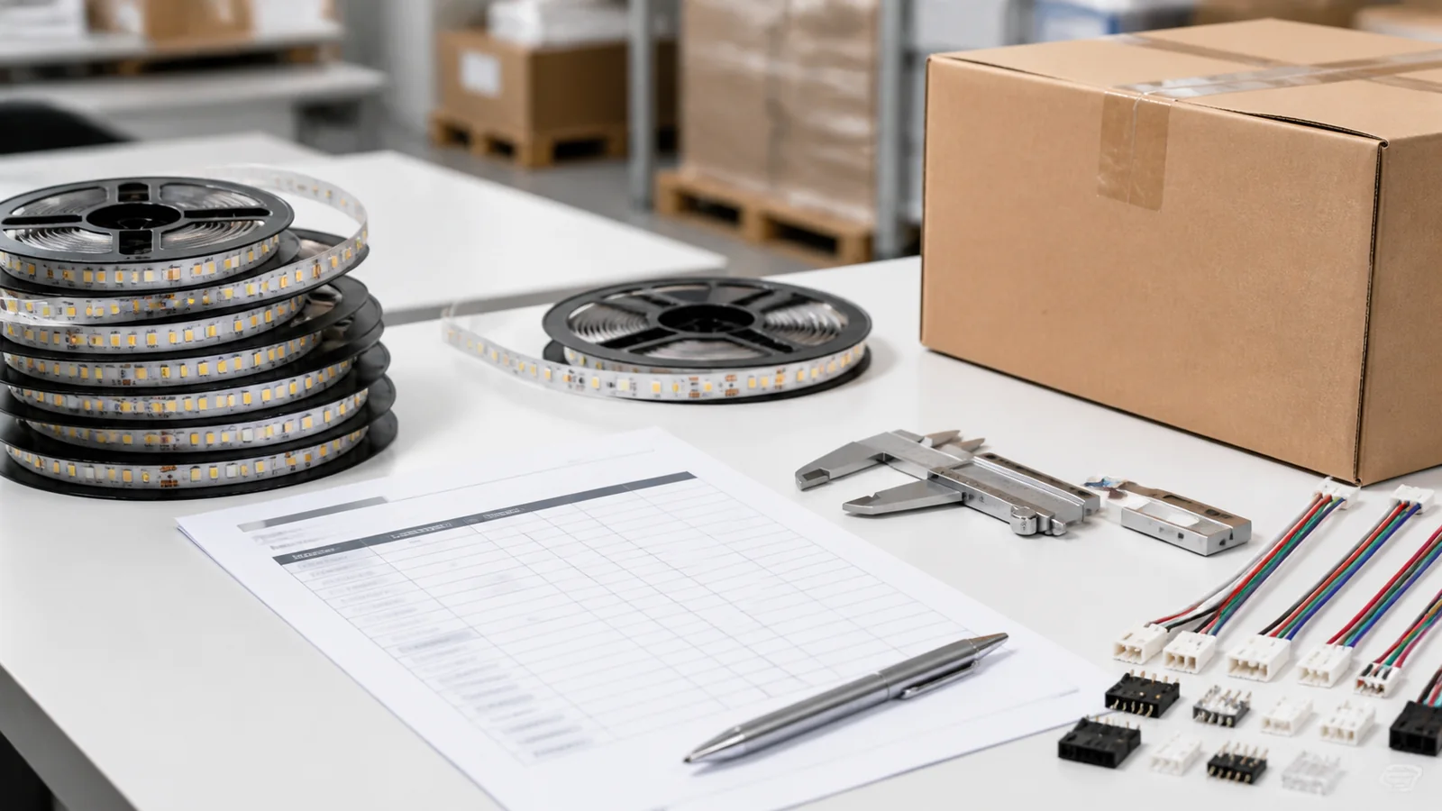
Information to put in the LED strip RFQ
Send the supplier a ceiling plan and a section detail along with the total meter quantity. State:
- room use and normal viewing direction;
- cove or recessed-profile dimensions;
- required CCT, CRI and dimming method;
- target output or approved reference sample;
- branch lengths, feed locations and total quantity;
- profile internal width, depth and diffuser type;
- ceiling-void temperature and driver access conditions;
- reel length, cut interval and joint expectations;
- packing labels needed for each floor, room or circuit;
- sample and mock-up acceptance process.
Ask for the exact model data before freezing the ceiling opening. Width and cut interval can change between visually similar strips. For an order inquiry, attach the drawings to the project quote form. The standard wholesale MOQ is 500m, and the final configuration should be confirmed before production.
Catalog & Sourcing Note
This article is prepared from our current product catalog and B2B specification workflow. Electrical, waterproofing and installation requirements vary by model and market, so confirm the final specification and approved sample before ordering.
Discuss Your Specification