A replacement LED strip must work with the existing supply voltage and control system. It also needs to fit the channel and remain within the installed electrical and thermal limits. Test its appearance beside the surviving installation before ordering a maintenance batch. Matching the CCT label or LED count alone leaves these checks unresolved.
This checklist covers low-voltage constant-voltage strip installations. Mains-voltage tape, constant-current light engines and proprietary pixel systems need their own model-specific replacement instructions. Isolate power before opening a fitting; a qualified electrician should inspect or change mains equipment.
Identify the existing system before removing the strip
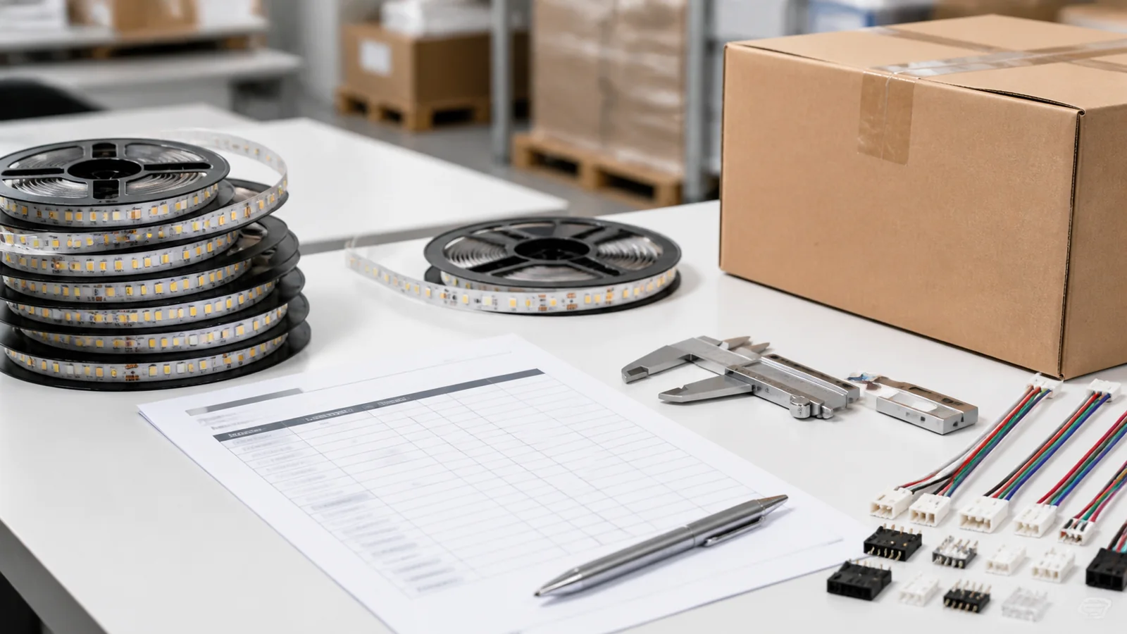
Photograph the markings on the strip and power supply, the controller and the connector orientation. Include the reel label if it has been retained, then record each branch’s location and length. A picture of the glowing line leaves voltage, power and control protocol unidentified.
Write down which components will stay: driver, dimmer, cables, channel and cover. If the original failure involved heat, a damaged connection or moisture, correct that cause before fitting a new strip. The troubleshooting checklist helps separate a strip fault from a supply or wiring fault.
If the rating remains unknown, obtain the original part record or have the system identified professionally. Do not apply a guessed voltage to see whether the strip lights.
Check voltage, control and the new branch load
Confirm the exact rated DC voltage of the replacement, the supply’s output type and its operating limits. A catalog entry stating DC12/24V describes voltage variants; it does not establish that one purchased reel automatically works at both voltages. Specify one voltage in the order.
Check whether the old system is single-color, tunable white, analog RGB or addressable. An equal pin count does not establish compatibility. Analog tape needs the correct channel arrangement and polarity; addressable tape also needs the correct protocol, data direction and supported controller settings. Use the controller selection guide when the control type is unclear.
Calculate the replacement load using its confirmed watts per meter and the installed length:
branch load (W) = installed length (m) × replacement power (W/m)
For an illustrative 4m branch, replacing 8W/m tape with 12W/m tape changes the calculated load from 32W to 48W. Those figures are an example, not a measurement of an existing site. Review the supply’s permitted load under its installation conditions, controller channel limits, cable capacity and joint ratings. Follow the equipment manufacturer’s thermal derating instructions.
Waveform Lighting’s strip support guidance confirms the need to match supply voltage and calculate strip load from power per unit length. Its product-specific cut intervals and thermal advice should not be applied to another manufacturer’s strip.
Check the channel and the finished light line
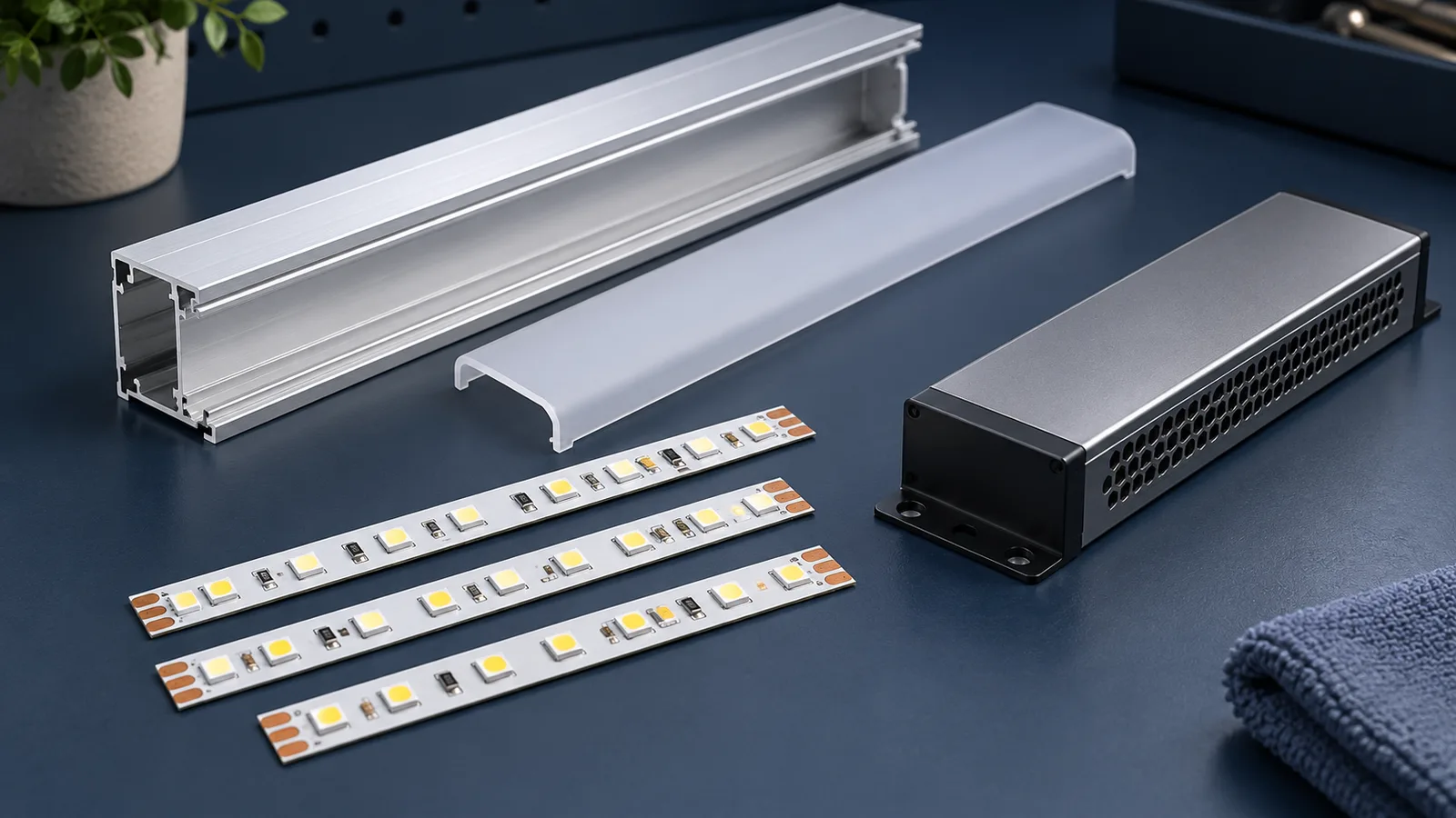
Measure usable channel width and space above the strip, including joints. Record the pad pattern, permitted cutting interval, cable exit and the cover part. A narrower PCB can fit while still placing the emitters differently inside the same optic. A larger connector can prevent the cover from closing.
Compare color with the final diffuser fitted and the nearby finish in place. The same nominal CCT and CRI do not guarantee an invisible boundary between a new reel and an older installed section. Keep the surviving section as a visual reference, but do not assume that it still represents the original product’s output or color.
For example, the catalog lists the 8mm 320LED CRI80 COB model at 10W/M and the 5mm 400LED CRI90 COB model at 8W/M. These are candidates to compare, not interchangeable replacements. Select the voltage variant and confirm cut length and construction before approving either.
Approve one replacement section in its real installation
Build a trial with the proposed strip and the components intended to remain. Have a qualified person check voltage and operation on the actual branch arrangement. Run full brightness and the normal dimming scenes, allow operating conditions to stabilize, and inspect heat and end-to-end uniformity within the component limits.
View the join from the customer’s normal position. Check reflections in glass and glossy finishes, not just the bare strip on a bench. If a short patch is conspicuous, compare replacing a complete visible run or zone. Record the cost and downtime of both approaches before buying a large maintenance stock.
Retain the trial model and its component list with the acceptance observations. Use the sample approval guide to connect that assembly record to the order.
Send enough information for a replacement quote
Include the original labels, selected voltage, control type, installed lengths by branch, watts per meter, profile drawing, cut interval, exposure and required appearance. State whether the request is a small repair or a batch for several properties. Flag every unknown instead of marking it “same as existing.”
LEDStripStar’s published standard MOQ is 500m per specification, so a single-site repair may not suit direct factory supply. For a planned maintenance batch, send the specification and quantity through the quote form; confirm availability and sample terms before scheduling the replacement work.
Catalog & Sourcing Note
This article is prepared from our current product catalog and B2B specification workflow. Electrical, waterproofing and installation requirements vary by model and market, so confirm the final specification and approved sample before ordering.
Discuss Your Specification