A low-voltage tape’s positive and negative connections form its operating circuit. They are not protective-earth connections. Check the mains driver, metal enclosure and other conductive parts for their separate earthing or bonding requirements. Follow the exact equipment instructions and the project’s electrical design; the number of wires on the strip does not settle this question.
A two-wire tape, a driver’s earth terminal and an aluminum channel each have a different role in the installation. The tape’s two leads do not justify leaving the driver’s required earth disconnected. An improvised connection from earth to the tape’s negative lead is not a valid substitute.
Distinguish protective earth from DC return
Protective earth, commonly identified as PE, forms part of an electrical protection arrangement. A DC negative or return conductor carries operating current in the output circuit. A controller terminal marked GND may identify a signal or supply reference. These labels do not make the conductors interchangeable.
For a specific example, the MEAN WELL LED power-supply installation manual distinguishes a Class I unit’s FG connection to protective earth from a unit marked Class II, ungrounded. The same manual requires disconnection before installation or maintenance. This is manufacturer guidance for its covered families, not a wiring instruction for an unidentified supply or evidence of an LEDStripStar driver offering.
Check the full model, safety-class marking and terminal diagram. A plastic case is not enough to identify Class II, and a metal case does not by itself establish the connection procedure. If the label is missing or conflicts with a seller’s explanation, pause installation and obtain the correct documentation.
| Part or marking | Question to resolve | Avoid this assumption |
|---|---|---|
| PE or protective-earth terminal | What earth arrangement does this equipment require? | A low-voltage output removes the mains-side requirement |
| DC negative or V- | What output return arrangement does the supply specify? | Negative is always the same as protective earth |
| Controller GND | Is it a supply return, signal reference or another documented connection? | Any ground-labelled terminal can accept building earth |
| Metal profile or enclosure | What protection and bonding does the completed assembly require? | Adhesive backing alone provides electrical protection |
| Class II marking | Do the exact unit and its installation follow the documented Class II arrangement? | Two input wires identify every unit’s safety class |
Review the driver and metalwork as an assembly
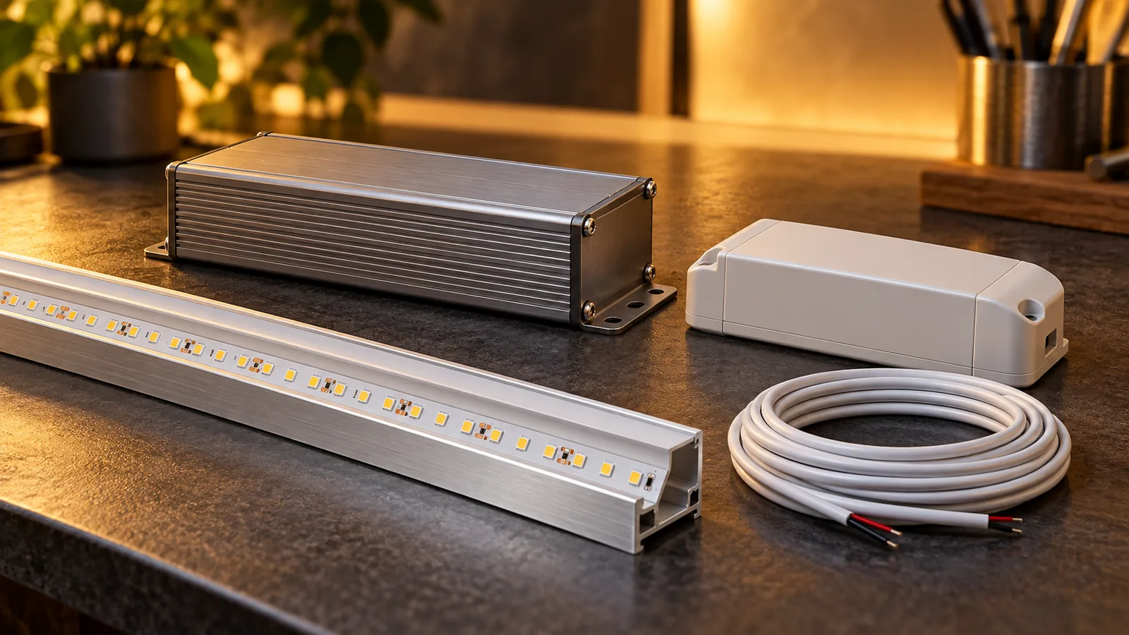
An aluminum profile supports mounting and heat transfer. It does not automatically become an approved electrical enclosure, nor does its presence alone tell the installer whether bonding is needed. The electrician must review accessible conductive parts, possible contact with mains wiring and the equipment’s protection arrangement.
Keep the driver, cable entries and mains terminals in the enclosure and locations specified by the equipment maker and electrical designer. Prevent sharp metal edges from damaging insulation, and provide the specified strain relief. A screw through the PCB or damaged cable can introduce a fault that a correct voltage label cannot prevent. The metal-mounting guide covers the physical mounting checks.
The 8mm CRI95 COB family lists DC12/24V variants. Select the required variant and compatible supply; that listing does not describe the driver’s safety class or establish the earthing of the completed installation. Do not connect either variant directly to building mains.
The AC220V range is a different system. It needs its own specified termination, insulation and protective arrangements, reviewed and installed by qualified personnel. The absence of a separate low-voltage driver is not permission to reuse a DC tape’s connector or mounting detail.
If exposed metal gives a tingling sensation, there is a burning smell or insulation is damaged, stop using the equipment and have the supply safely isolated and inspected. Do not test suspected leakage by touch or remove an earth conductor to stop a nuisance symptom. This article does not provide live electrical test procedures.
Put the protection arrangement in the project records
Have the electrical professional confirm the mains equipment, output arrangement, enclosures and any required bonding before ordering. Obtain documentation for the exact order codes. A photograph of a similar driver is insufficient.
- Identify the strip architecture, selected voltage, driver and controller.
- Record the equipment markings and required protective connections.
- Agree the location and enclosure of mains equipment and the low-voltage cable route.
- Resolve metalwork, cable-entry, strain-relief and bonding details in the installation design.
- Have qualified personnel carry out the required commissioning checks and record the results.
- Keep those records and replacement references with the handover documents.
Use the quotation form for the strip specification, with supply ownership and unresolved installation questions stated separately. Standard products start at 500 meters; custom products start at 2,000 meters. A strip quotation cannot replace the project’s electrical protection design.
Catalog & Sourcing Note
This article is prepared from our current product catalog and B2B specification workflow. Electrical, waterproofing and installation requirements vary by model and market, so confirm the final specification and approved sample before ordering.
Discuss Your Specification