An LED strip can look warmer, cooler or simply less bright after a diffuser is fitted because the cover changes the transmitted light and its distribution. Surrounding finishes and viewing conditions can also change what you see. Test the same strip with and without the cover under controlled conditions before blaming the LED batch or ordering a different CCT.
There is no universal color-temperature correction for an “opal” cover. The exact material, thickness and formulation matter. This article concerns a color or tint difference; for visible LED dots, use the diffusion design guide.
Separate the cover, source and room
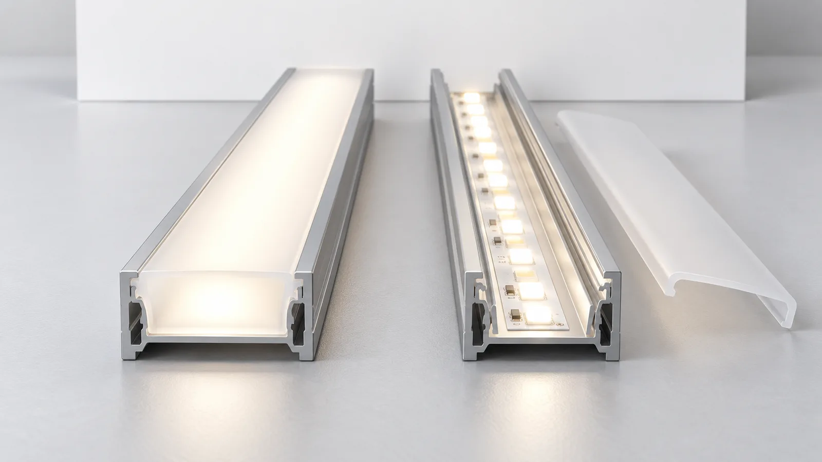
The bare strip and the finished fitting are different optical assemblies. A translucent cover can absorb light and redistribute it. Its appearance name does not define its spectral transmission or the resulting color.
ACRYLITE’s technical guidance on white and colored acrylic explains that pigment type and concentration affect color transmission, while thickness affects transmission in its translucent white sheet range. It recommends evaluation under intended end-use conditions. This supports testing the actual optic; it does not supply a correction value for every acrylic or polycarbonate channel cover.
The illuminated surface affects a reflected light line’s appearance. Include the actual timber or painted finish and adjacent lighting in the comparison. A phone’s automatic white balance can change between shots, which makes photographs unsuitable for quantifying a CCT shift on their own.
If the difference develops only after operation or appears mainly at one end of a long branch, investigate supply conditions and temperature as well. Stop using a fitting that shows damage or abnormal overheating. A color comparison cannot clear an electrical fault.
Use the same source and change one item
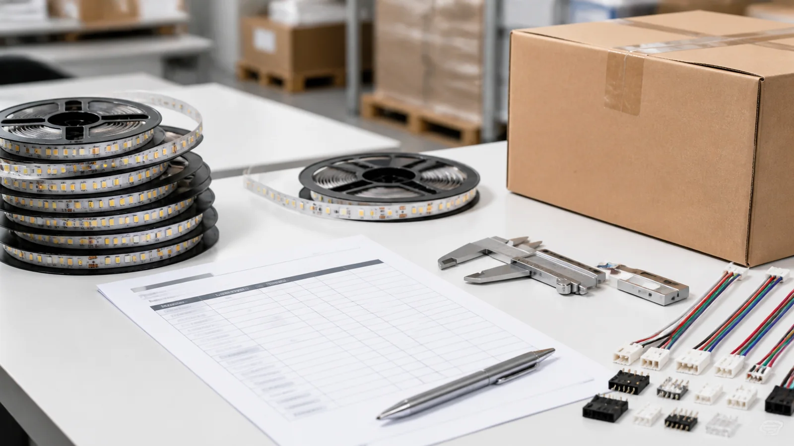
Keep the strip, supply, control setting and channel position fixed. Use a safe sample assembly with the correct voltage and mounting; isolate power before moving parts. Do not power a tightly wound reel for this test.
- Observe the uncovered assembly against a neutral reference surface. Record the ambient lighting, viewing distance and operating state.
- Isolate power, fit the intended cover, then observe it under the same conditions. Use comparable stabilized operating conditions for both observations.
- If another cover is proposed, repeat with that exact part on the same assembly. Avoid changing the strip at the same time.
- Compare two strip samples through the same cover only after isolating the cover’s effect. Use matched supply and operating conditions.
- Put the chosen assembly beside the real timber, paint, merchandise or display panel. Confirm the result from the normal viewing position.
For photographs, keep exposure and white balance fixed between comparisons. Retain them as a visual record, not a calibrated measurement. If acceptance requires numerical color matching, agree an instrument method and geometry with a qualified tester. Record assembled chromaticity and CCT where required; a lux meter measures illuminance, not chromaticity.
Choose the next check from the observation
| Observation | Next check |
|---|---|
| The same source looks different whenever one cover is fitted | Check that cover’s part number, formulation and optical information |
| Two strips differ through the same cover | Compare source color and electrical or thermal conditions |
| The neutral reference looks acceptable but the finished display does not | Compare the actual surface and adjacent lighting |
| The difference varies along a long branch | Check feed voltage and connections before changing the CCT order |
| Only photographs show a large difference | Check camera settings and compare directly under fixed conditions |
The observations help locate the difference, but further checks are needed to establish a material or LED fault. Swapping a cover can change operating temperature. Your visual adaptation can also differ between sequential views. If the difference matters to acceptance, measure the complete assembly; a picture cannot establish the correction to order.
Do not automatically compensate by ordering cooler tape or increasing watts per meter. A change may fix one viewing condition while creating a mismatch elsewhere or exceeding the existing thermal design. Compare the alternatives in the finished detail first.
Approve the optic and strip together
Record strip model and voltage, selected CCT, channel section, cover part and thickness, viewing condition, surrounding finish and accepted control settings. Attach the accepted assembly reference to the order. A later cover substitution needs a new comparison even if it is also described as “milky.”
The 8mm 320LED CRI95 COB model is one catalog candidate for a white-light display. Its stated CRI does not establish color neutrality through a particular cover. Select the voltage and CCT variant, and evaluate it in the intended profile.
For a quotation request, provide the cover reference or sample, product dimensions and intended finish. State any measured acceptance target separately from the visual sample. The supplier can then identify what still needs confirmation before the assembled appearance is approved.
Catalog & Sourcing Note
This article is prepared from our current product catalog and B2B specification workflow. Electrical, waterproofing and installation requirements vary by model and market, so confirm the final specification and approved sample before ordering.
Discuss Your Specification