LED strip lights are widely used in commercial lighting, architectural projects, retail stores, hotels, and cabinet applications. They offer flexibility, energy efficiency, and design versatility that traditional lighting cannot match.
But incorrect installation can cause serious problems:
- Uneven brightness along the strip
- Voltage drop on long runs
- Overheating and premature failure
- Shortened lifespan
- Customer complaints and project delays
This guide explains how to install LED strip lights, where to cut an LED strip, how to connect sections and how to wire the system for bulk and professional projects. Always follow the product datasheet and local electrical rules; mains-voltage work must be performed by a qualified installer.
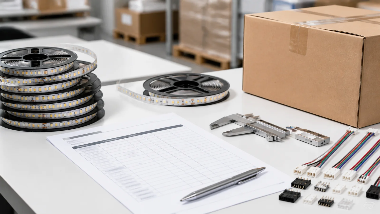
Tools & Materials Needed
Before starting any installation, prepare the following materials:
| Category | Items |
|---|---|
| LED Strip | LED strip reel (12V or 24V DC) |
| Power Supply | Matched LED driver with 20% capacity headroom |
| Mounting | Aluminum profile with diffuser cover |
| Wiring | 18–20 AWG wire, connectors, soldering kit |
| Surface Prep | Isopropyl alcohol, clean cloth |
| Tools | Measuring tape, sharp scissors, screwdriver, level |
| Optional | Dimmer, controller, amplifier for long runs |
Selection note: 24V often reduces current and voltage drop compared with 12V at the same power, but the correct voltage still depends on cut length, controls, run length, and the existing electrical system.
Step 1 – Measure and Plan the Layout
Accurate measurement is the foundation of a clean installation.
What to do:
- Measure the total length of the installation area
- Plan where power will be injected (beginning, end, or both sides)
- Identify corners, turns, and connection points
- Calculate the total wattage requirement
For longer runs, calculate voltage drop and plan power injection rather than relying on one universal distance rule. Maximum powered length varies by voltage, wattage, copper weight, PCB width, cable size and acceptable brightness variation.
Pro Tip: Draw a simple layout diagram before ordering. Mark power supply locations, strip lengths, and connection points. This prevents costly on-site adjustments.
Step 2 – Choose the Right Power Supply
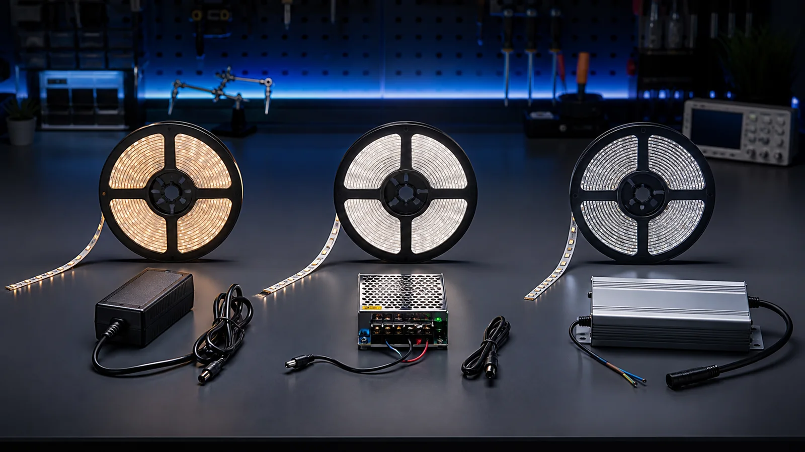
An undersized or poorly matched power supply is a common cause of unstable LED strip systems.
Calculation formula:
Strip wattage per meter × total meters × 1.2 (safety margin) = required PSU wattage
Example: A 14.4W/m strip installed over 10 meters: 14.4 × 10 × 1.2 = 172.8W minimum power supply
Key selection points:
- Always add 20% headroom above actual load
- Use a driver with a protection rating and enclosure suitable for the actual outdoor installation
- Choose a reputable driver with the required safety approvals, dimming protocol and environmental rating
- Match the voltage: 12V strip → 12V driver, 24V strip → 24V driver
Step 3 – Prepare the Surface
LED strips need a clean, dry, and smooth surface for proper adhesion and heat dissipation.
Surface preparation steps:
- Clean the mounting surface with isopropyl alcohol
- Remove any dust, grease, or moisture
- Let the surface dry completely before applying the strip
- For painted or textured surfaces, lightly sand first
For aluminum profiles: Clean the inside channel before inserting the LED strip. Any debris will cause uneven contact and hot spots.
Important: The 3M adhesive on LED strips is pressure-sensitive — it bonds best to clean, non-porous surfaces. On rough or dusty surfaces, the strip will fall within weeks.
Step 4 – Cut and Connect LED Strips
LED strips can only be cut at the designated cut marks printed between copper pads. The interval depends on the circuit design, so check the exact model rather than assuming a fixed LED count.
Cutting rules:
- Use sharp scissors or a craft knife
- Cut only on the marked copper pads
- Never cut between marks — this will damage the circuit
For cut-interval planning, offcut reuse and special protected constructions, use the dedicated guide: Can you cut LED strip lights?
Connection methods:
- Soldering — Compact and reliable when carried out with the correct temperature, pad preparation and strain relief.
- Solderless connectors — Faster for field work when the connector matches PCB width, pad layout, current and IP requirement.
For corners and turns, use flexible wire jumpers between strip segments rather than bending the strip itself. Bending at sharp angles damages the copper traces and causes failure points.
Step 5 – Install Aluminum Profiles
Aluminum profiles are strongly recommended when the strip’s thermal design or finished appearance requires them. Follow the strip manufacturer’s mounting and temperature limits.
Why aluminum profiles matter:
- Heat dissipation — Aluminum can help conduct heat away from the PCB; the actual temperature improvement depends on profile size, airflow, mounting surface and strip power.
- Light diffusion — The milky cover eliminates visible LED dots, creating a smooth, even light output.
- Physical protection — Protects the strip from dust, impact, and moisture.
- Clean appearance — Gives the installation a finished, professional look.
Installation steps:
- Mount the aluminum channel to the surface using screws or adhesive
- Insert the LED strip into the channel (adhesive side down)
- Click the diffuser cover into place
- Connect wiring through end caps
Profile selection guide:
| Application | Profile Type |
|---|---|
| Surface mount (cabinets, shelves) | Slim surface profile |
| Recessed into ceiling/wall | Recessed channel |
| Corner/cove lighting | 45° angle profile |
| Suspended linear light | Pendant profile |
Step 6 – Test Before Final Fixing
Always test the entire installation before permanent mounting.
Test checklist:
- Power on the full strip length
- Check for even brightness along the entire run
- Verify color temperature matches the specification
- Look for any flickering or dark spots
- Measure voltage and brightness at the far end; compare the result with the project’s allowable variation and add feeds if needed
- Let the system run for 30 minutes and check for overheating
Only proceed to final fixing after all tests pass. Troubleshooting after permanent installation is expensive and time-consuming.
Common Mistakes to Avoid
Based on our experience manufacturing LED strips for projects worldwide, these are the most frequent installation errors:
1. No power-injection plan on long runs A feed layout should be calculated from load, cable size, run length and allowable voltage drop. Long or high-power runs may need parallel feeds or multiple injection points.
2. Choosing voltage without checking the complete system 12V can suit short sections and small cut intervals, while 24V often reduces current for the same power. Choose based on the driver, controls, cable and required run length.
3. Skipping aluminum profiles Direct mounting may be acceptable for some low-power models and suitable surfaces, but higher-power strips often benefit from an aluminum profile. Verify the product’s thermal requirements.
4. Undersized power supply Running a driver at 100% load causes overheating and early failure. Always specify 20% headroom.
5. Poor soldering joints Cold solder joints are the #1 cause of connection failures in the field. Use proper soldering technique and flux.
6. Ignoring IP rating requirements Using IP20 strips in damp environments (kitchens, bathrooms, outdoor) will result in failure within months. Match the IP rating to the installation environment.
Need help with LED strip specifications for your project? Our engineering team provides technical support for bulk orders. Contact us or message us on WhatsApp for fast response.
Catalog & Sourcing Note
This article is prepared from our current product catalog and B2B specification workflow. Electrical, waterproofing and installation requirements vary by model and market, so confirm the final specification and approved sample before ordering.
Discuss Your Specification